
JESTLED is an experiment in bridging the real world to virtual reality. Oculus Quest controllers are used to conduct a display of vibrant colourful lights along a strip of LEDs.
Motivation
During the course, we learnt about using Wekinator to create machine learning models to turn complex sensor data into usable output values for artistic creativity. For this project, I wanted to make use of the controllers on the Oculus Quest virtual reality headset. I had only recently tried VR and was very impressed at how accurate and responsive the controllers were for use within 3D space and I wanted to see if I could use them for control outside of the virtual world.
My original plan was to use them to control a musical performance, but I changed my mind to instead use them to manipulate light patterns on an LED strip secured above the window frame in my lounge. I see this initially as a nice home installation but it has a lot of flexibility and could be installed in a public setting.
Background and inspiration
I became aware of programming LEDs when I met Robin Baumgarten at the London Hackspace. He was working on a project which became Line Wobbler. At the time it was in very early stages and wasn’t that impressive, but I next saw it at the Victoria and Albert Museum as part of their Parallel Worlds exhibition and it was amazing. The colours are bright and refresh rates are very fast on a strip of LEDs, and so they can be used in creative ways.
I used an LED strip for my previous project - City Sunrise for Physical Computing as part of this degree course. Although I was happy with the outcome, I learned quite a lot about using LED strips which I wanted to take forward into another project. Previously I used 5v strips which meant I wasn’t able to power all the LEDs to full brightness simultaneously. For this project, I used a 12v strip which overcomes this limitation and produces full vibrant colours.
I also switched from using a Metro M0 Express (similar to Arduino) to using a Raspberry PI v4 (RPI). I had heard that connecting LEDs to an RPI wasn’t possible, but it turns out it can be done by turning off the soundcard and redirecting that output to the LEDs as a pulse width modulation (PWM). I did some tests, found it worked and decided to proceed with the RPI as it was much easier to work since it has WiFi built-in and I could even remote desktop to it.
I was also inspired by L.A.S.E.R Tag from Graffiti Research Lab. This project allowed people to graffiti using a high powered projector and a laser. The software would track where the laser had been and use this point as a cursor to control the projection of light. I like the connection of the physical touch with the remote action.
In a different vein, I saw Imogen Heap perform at the Roundhouse, where she used a set of programmable gloves as her instrument. I presume they must employ a form of ML similar to Wekinator since she had a wide variety of gestures which she performed to drive musical and lighting outputs. The lighting setup and gestures were quite specific to the venue so I would imagine the model was trained specifically for the performance. It was an impressive setup and worked very well on stage.
Implementation
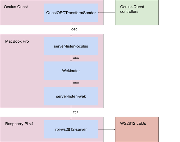
I started experimenting to see if OSC output from the Quest was even possible. I was fortunate that someone had already written QuestOSCTransformSender and I was able to side-load it onto the Quest.
The output is sent as six different OSC messages with the first string argument used to differentiate between them. It sends position and rotation as both global and local transforms for the headset (HMD) and both controllers. Since I didn’t plan to wear the headset I wrote a Node.JS application to receive the OSC messages and filter them to the local values for both handsets. I then combined these into a single message which has 14 floats for the local positions and rotations of both controllers. I looked at using WekiInputHelper for these adjustments but it didn’t seem like it was possible to split and combine different messages.
There are 7 variables for each controller: in addition to the standard six degrees of freedom (position x,y,z and rotation x,y,z) they also include w representing the rotation of the controller along the axis of the person’s wrist.
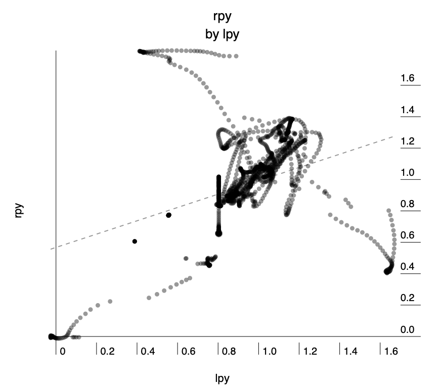
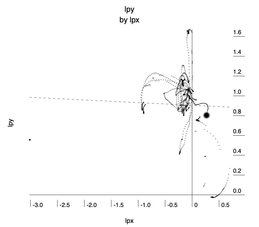
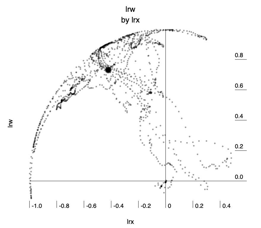
I wrote code that could collect OSC and output it to analyse in existing software before proceeding further so that I had an idea of what kind of values to expect. I wrote the values to sample-data.csv (included in zip) and used Wizard - Statistics & Analysis to analyse it.
The following three charts show some of the analysis. I was able to see that the values are distributed around zero as the origin and go roughly ±1 from there. The wrist rotation looked like it might be a useful feature to have so I decided to include it in my OSC messages. The data seems somewhat noisy, however from playing games on the Quest I’ve found the tracking to be exceptionally good, so I put the noise partly down to minor movements in my hands and body while conducting the tests.
From here I used Wekinator to make some rough models so I could check that moving the controllers could produce something like the intended effect and it seemed like it would work well, with occasional inconsistencies, however, it seemed a reasonable result and so I moved on to coding the LEDs for output.
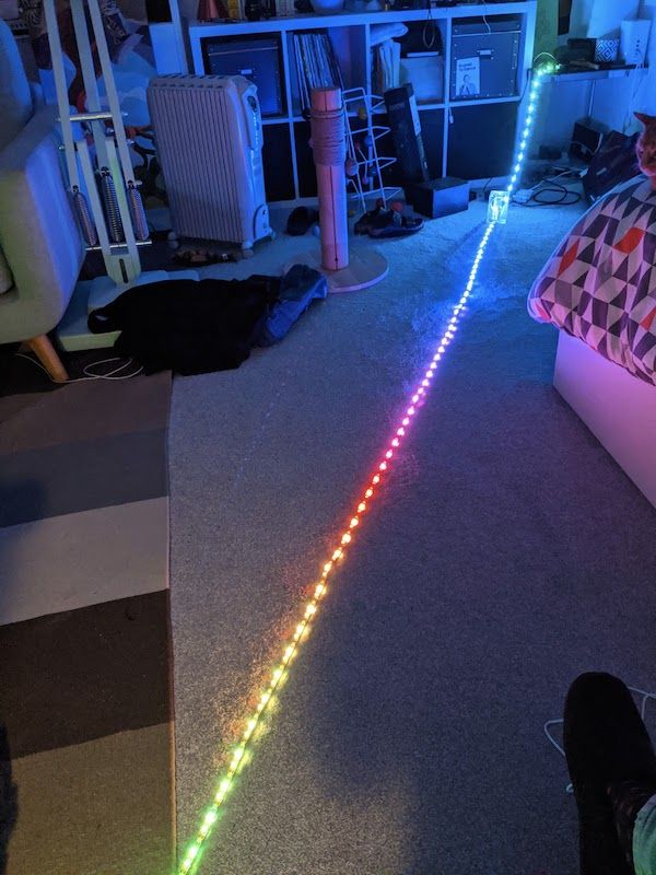
I had ordered a 12v LED strip from China early in the year and was lucky that it arrived just before the lockdown began. After some experimentation I got it working with my Raspberry PI using this PWM driver and then better still I found that a server already existed so I could communicate with it using TCP.
I tested sending commands over TCP using Node.JS and that worked well too. This helped me a lot as it’s the language I’m most familiar with.
I started by writing code that would accept a float from 0 to 1 and map it to the position along the LED strip. Once I had that working I was able to test end-to-end using Wekinator and it roughly worked.
From here it was a case of adding the second controller and making incremental improvements to the code. I imported the D3 library as it has excellent colour control which I used for interpolating between colours and also for adjusting the gamma which is critical when using LEDs since the response curve is non-linear.
I wrote code which listens to the output from Wekinator in a similar way to a game engine by using two independent loops. The “game” loop runs as fast as it can and receives messages which it uses to update position with a time delta so that it is independent of how fast the hardware is running. The render loop is set to run every 20 milliseconds and it takes the current state and turns it into commands for the LEDs. I found that this gave excellent responsiveness without causing any render queues on the Raspberry PI.
I ended up with three variables that could be set. They adjust the x position of the blob of light, the size of the blob and the colour.
Model training and usage
So far I had been testing with direct input to simulate the outputs I would expect from Wekinator. I needed an extra set of hands so for the training phase my girlfriend used the Oculus controls and I took care of the recording with Wekinator.
I tried a polynomial regression initially for the x-position since I thought that the radius of the arm would mean a curve would be the best fit, but after a lot of testing found that using linear regression with just a single variable and data only recorded for the extremities of the LED strip gave the best result for both performance and accuracy. The formula came out as 1.2826 × lpx + 0.5865, (where lpx is the x-value from the handset). I ran cross-validation accuracy and got 0.01 RMS.
For size I used the height of the controllers, however, the rotation of someone’s hands varies quite a lot by how high they hold their hands and also depending on if their hands are in front of them or to the side. For this, I settled on using a neural network regression with the three controller rotation values and one hidden layer. We trained at three different heights for different sizes across the range of x-position values.
For colour, initially, I wanted to use the rotation of the wrist, but during training, I found that rotating the wrist would confuse the previous model for controlling size. After dwelling on this issue for some time I realised that it was because the origin of the position of the values from the controller is set slightly above the hand.
I didn’t have enough time to work out how to fix this in Unity, so instead, I looked for a different mechanism. I came up with the idea of using a palette of colours which the user could point to on the ground. This could be set up as physical objects and you select the colour by simply pointing to an object of the colour you want.
I used a classification model for this with five classes. Class 1 was anything above waist height and in the code, this simply preserved the current colour. The other colour classes were then created by pointing downwards. I used a k-nearest neighbour model with one neighbour for this since the boundary didn’t need to be precise and it was clear when you changed class and how to change back.
One thing we discovered during training was that turning 360° would invert some of the controls. It was very confusing as it happened occasionally and I initially thought it was that the model had gone wrong — it took a while to realise that it could be fixed by just turning back the other way.
Self Evaluation
Overall I’m extremely happy with this result. It’s really fun to use and gives immediate pleasure. I would have liked to do more user testing but social distancing made that impossible. Prior to taking this course, I would have just used simple mapping of the values, which would have worked ok for the x-position but everything else would have been nearly impossible without using Wekinator for machine learning. Now that the model is set up, if I move the equipment then retraining takes only a couple of minutes
If I had more time I would have recompiled the Unity project to fix the transform of the wrist rotation point so that I could use that as a useful input. I would also love to spend more time on adding extra effects to the LEDs.
Appendix
Equipment, software and architecture
For this project I used the following:
Hardware
- Oculus Quest headset and controllers
- Raspberry PI v4
- WS2812 300 LED 12v strip with power adapter
- MacBook Pro laptop
Third-party software
- Wekinator - For training and running machine learning model to transform input values to output values
http://www.wekinator.org/ - QuestOSCTransformSender - For emitting Oculus Quest controller data in OSC https://github.com/sh-akira/QuestOSCTransformSender
- Rpi-ws2812-server - For controlling WS2812 over TCP on Raspberry PI
https://github.com/tom-2015/rpi-ws2812-server - Osc-js - For listening and transforming OSC data from Quest, sending to Wekinator, and then receiving from Wekinator
https://www.npmjs.com/package/osc-js - D3.JS - For colour control and interpolation
https://github.com/d3/d3 - Node.JS v12 - including FS, Net, Performance modules from the standard library
https://nodejs.org/docs/latest-v12.x/
Architecture
The values from Oculus Quest controllers are emitted by QuestOSCTransformSender and sent to my MacBook where server-listen-oculus.js receives them. The original messages are sent separately for left and right controllers and includes a string to specify which controller and seven float values. I turn these into a single message which has 14 floats for both controllers combined as this makes it easier to deal with in Wekinator.
I use the models in Wekinator to transform the data for the outputs and this is then sent to server-listen-wek.js which uses those values to control parameters within led.js which then sends messages over TCP to rpi-ws2812-server running on the Raspberry PI. This then sends PWM signals over pin 18 which controls the WS2812 LEDs directly.
Running the project
The code is available at https://github.com/aubergene/jestled
You will need to have Node JS v12, Wekinator, a Raspberry PI v4 running rpi-ws2812-server and a strip of WS2812 LEDs connected and working. It might well work with other versions of software and hardware but hasn’t been tested. Additional instructions can be found in README.md.