

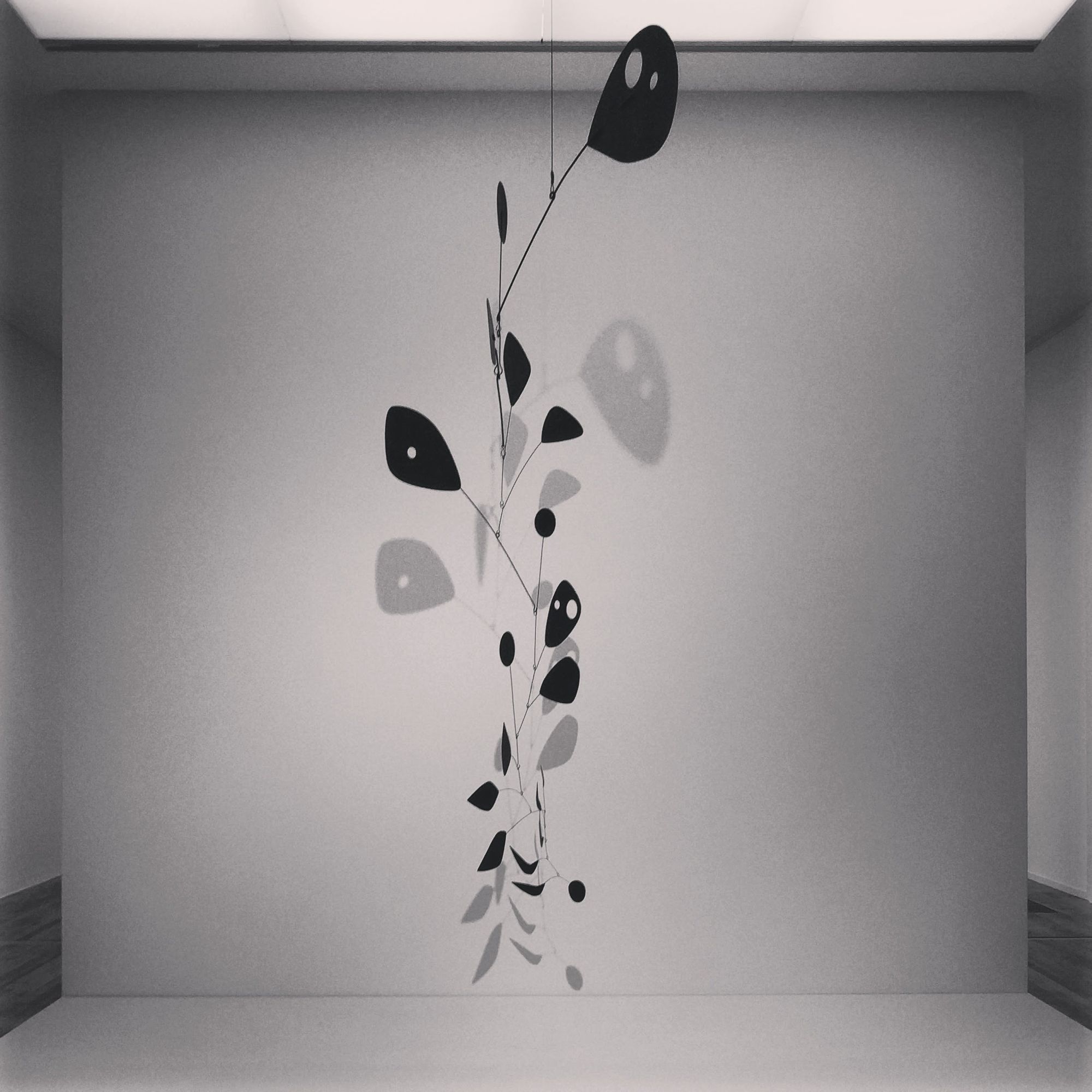
Genetic Construction is a mobile created using genetic and linear algorithmic processes. Taking inspiration from the works of Munari and Calder, it also draws on ideas from the centennial constructivist movement looking at art grounded in the material reality of space and time.
Introduction
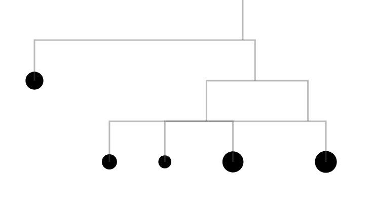
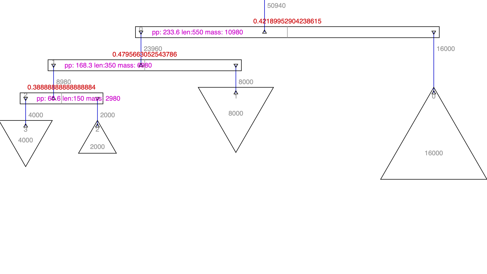
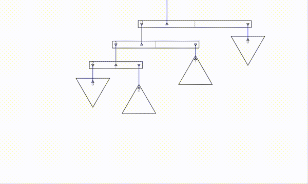
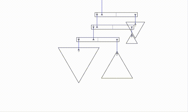
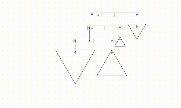
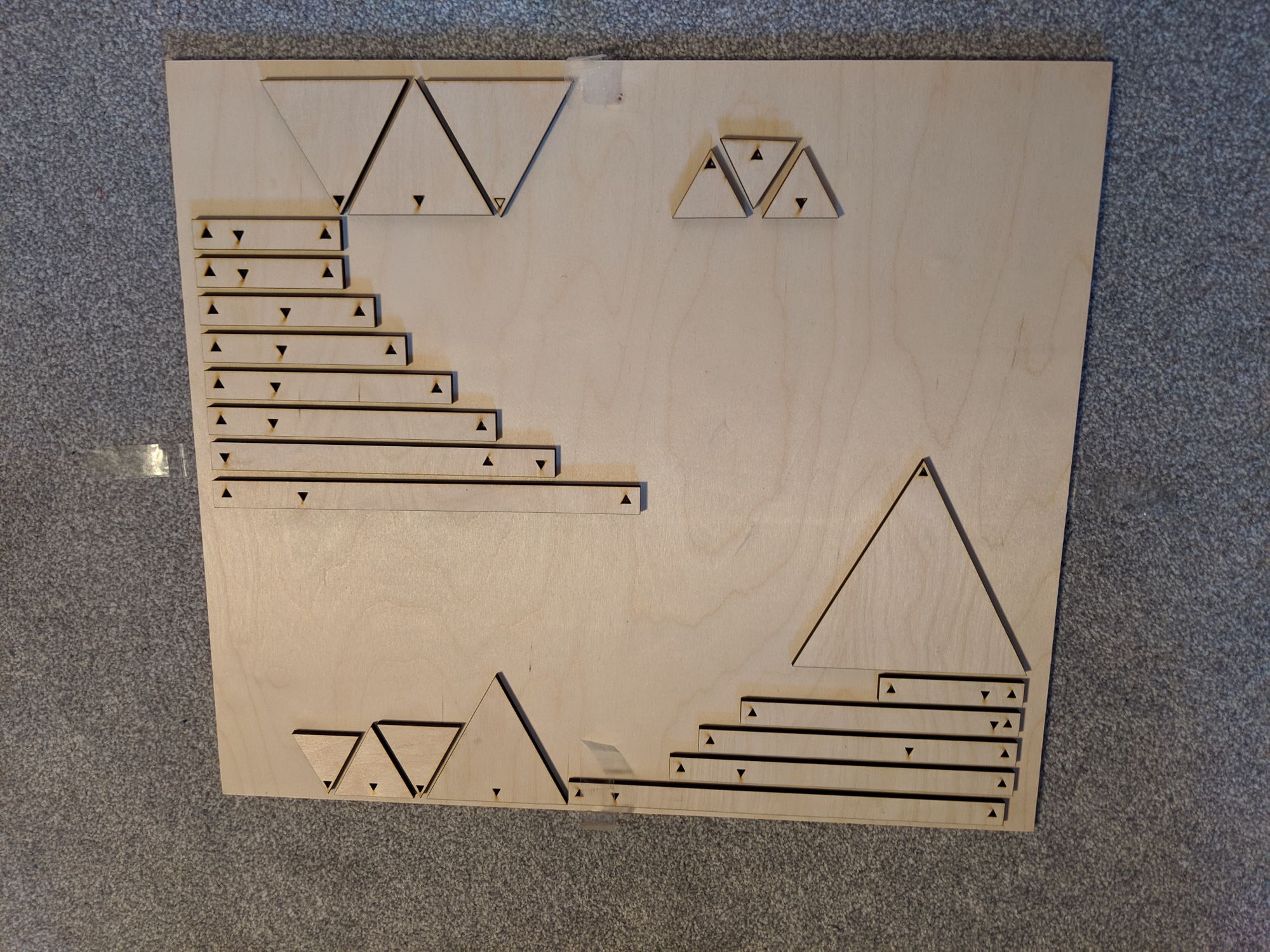
The work comprises three types of element: the equilateral triangular masses, the pivotal beams and the thin transparent connecting monofilament threads. The elements are represented by a tree structure within the code, where calculations determine the position of the pivot point along the beam to ensure the tree-like structure will balance. A population of random variations is generated and fed into a genetic algorithm which selects the fittest individuals to proceed to the next generation. It seeks to reduce any clash or entanglement of the components whilst also looking to optimise the diversity of masses and complexity of structure.
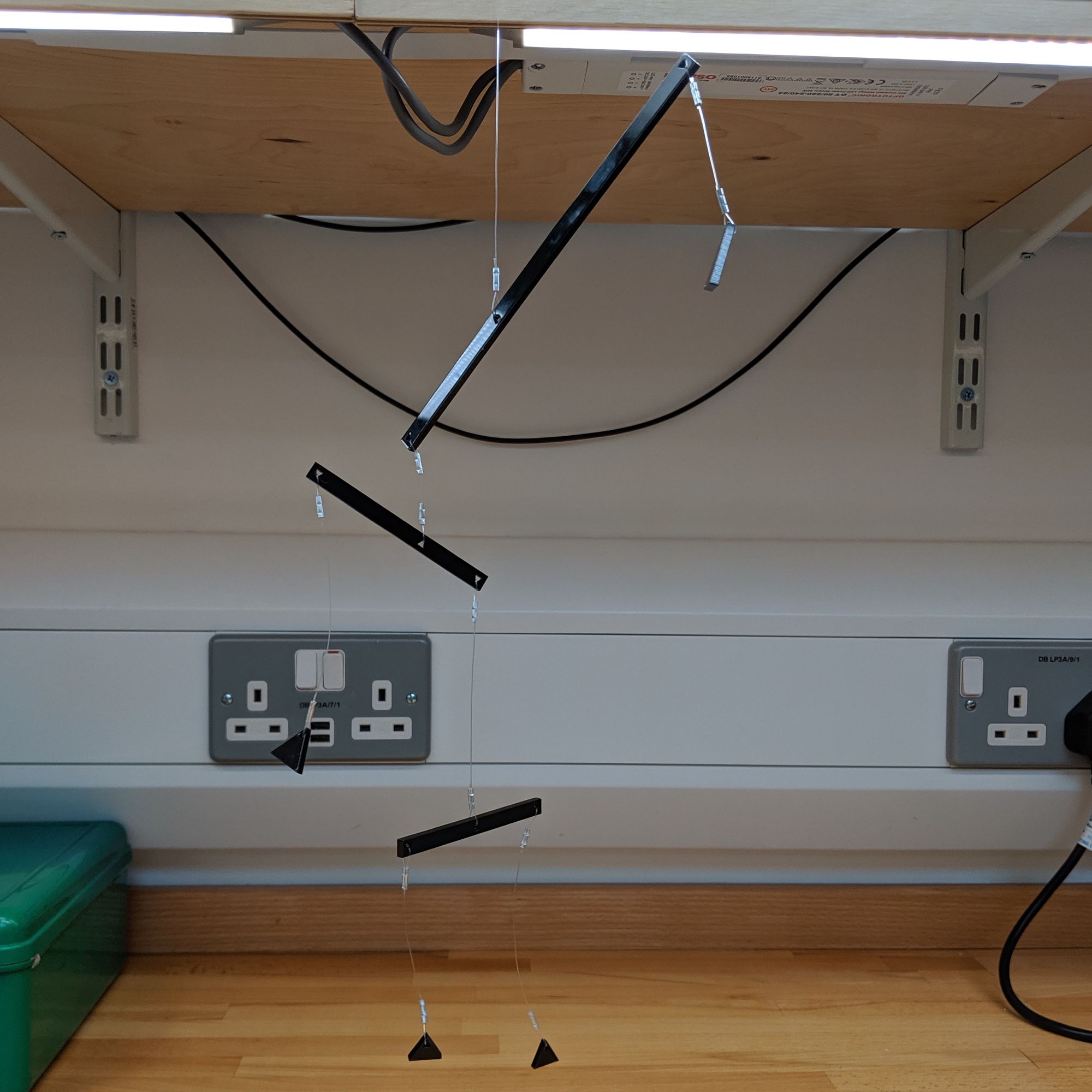
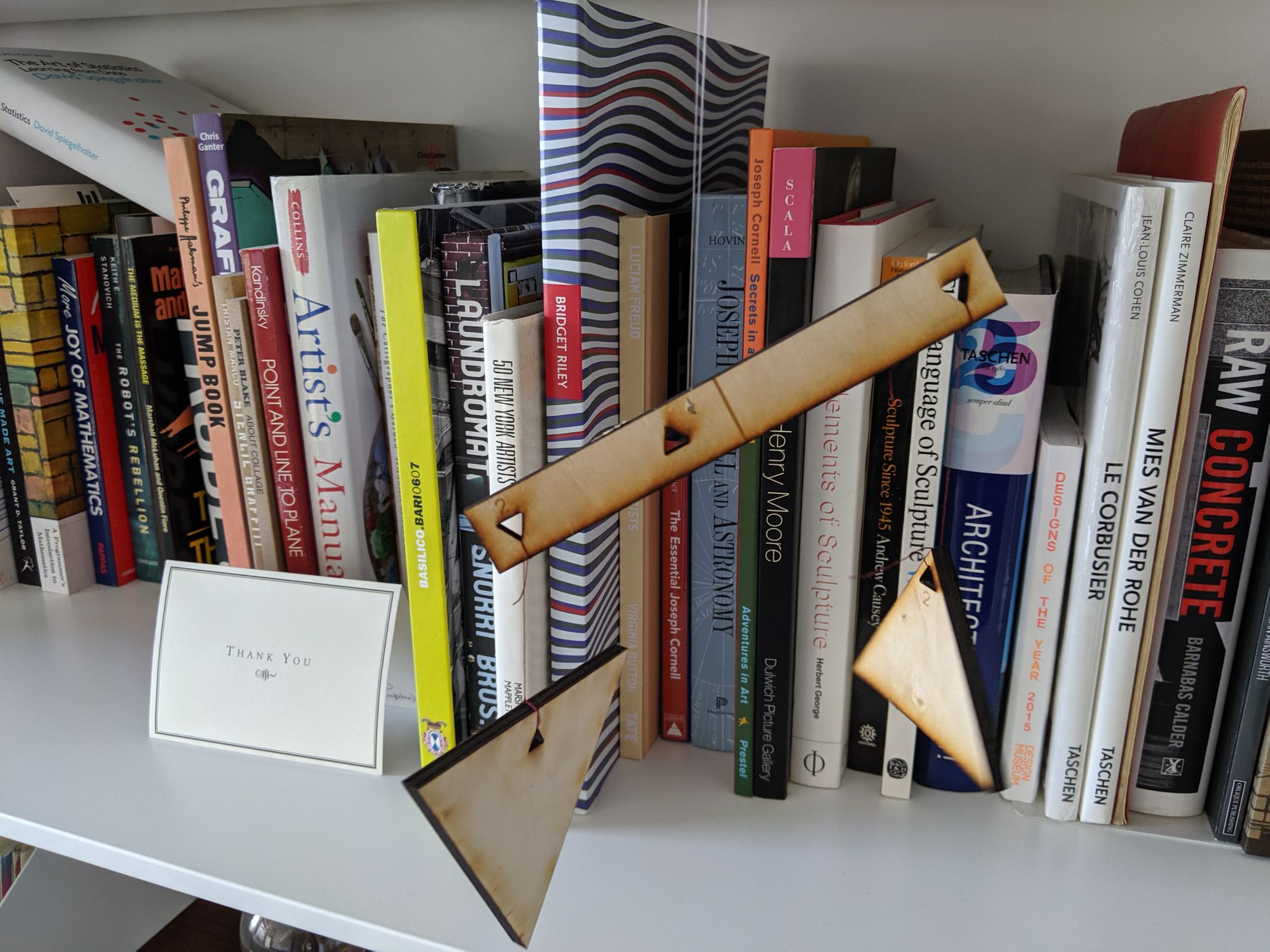
After many generations of genetic selection, I picked an individual from the population and used the generated blueprint to laser cut the pieces and assemble the mobile structure. It is painted with blackest black BLK 3.0 paint, as I wanted the piece to be invisible, for it to create a subtractive, negative space where its presence is that of what is removed from view — like floating voids in space.
Concept and background research
As a part-time student I have the luxury of having two summer term projects. This year I knew in advance that I wouldn't be able to attend the end of year art show as I would be going to Ars Electronica. Therefore I wanted to create a project that I could be certain would be ready before I left and that would work seamlessly at the show in my absence.
I had seen the Alexander Calder: Performing Sculpture show at Tate Modern in 2015 and loved it. I've been fascinated by kinetic art since I was a child and have admired the works of Bruno Monari, Alexander Calder, and other kinetic artworks. It had been a long-standing ambition to create mobiles and this seemed like the ideal opportunity to begin my explorations.
Technical
My work on this project was broadly split across two parts: writing software to generate the layout for a mobile and physical construction of the mobile. Both presented challenges which I didn't expect.
F = Md (force = mass × distance)
I initially thought that creating an algorithm to balance a beam would be easy since it should simply be applying the above Newtonian law we were taught during GCSE physics. However, it was more complex than I that, as usually these physics exercises assume a perfect straight massless beam, and in real life the mass of the beam matters!
I researched balanced construction techniques and discovered the Whippletree, which is used to tether horses (and in other situations) to spread the forces evenly.
I experimented by iteratively experimenting with balancing structures made materials from around the home. I was somewhat surprised by how delicate it was to find the pivot point.
View post on imgur.comWhile performing these physical experiments, I also began trying to work out how to draw a mobile. I thought I might be able to use L-Systems again as I had used them before in my theory project for drawing snowflake shapes. However, it wasn't easily possible since the recursive nature of L-systems made calculating the balance point complex. Instead, I decided to use a tree structure with the assistance of D3 Hierarchy.
View post on imgur.comI decided to create my project using JavaScript since it is the language with which I am most familiar and I wasn't expecting any significant performance issues. Also, JavaScript and the web as a platform has advanced considerably in the last few years which has made writing more complex projects much easier.


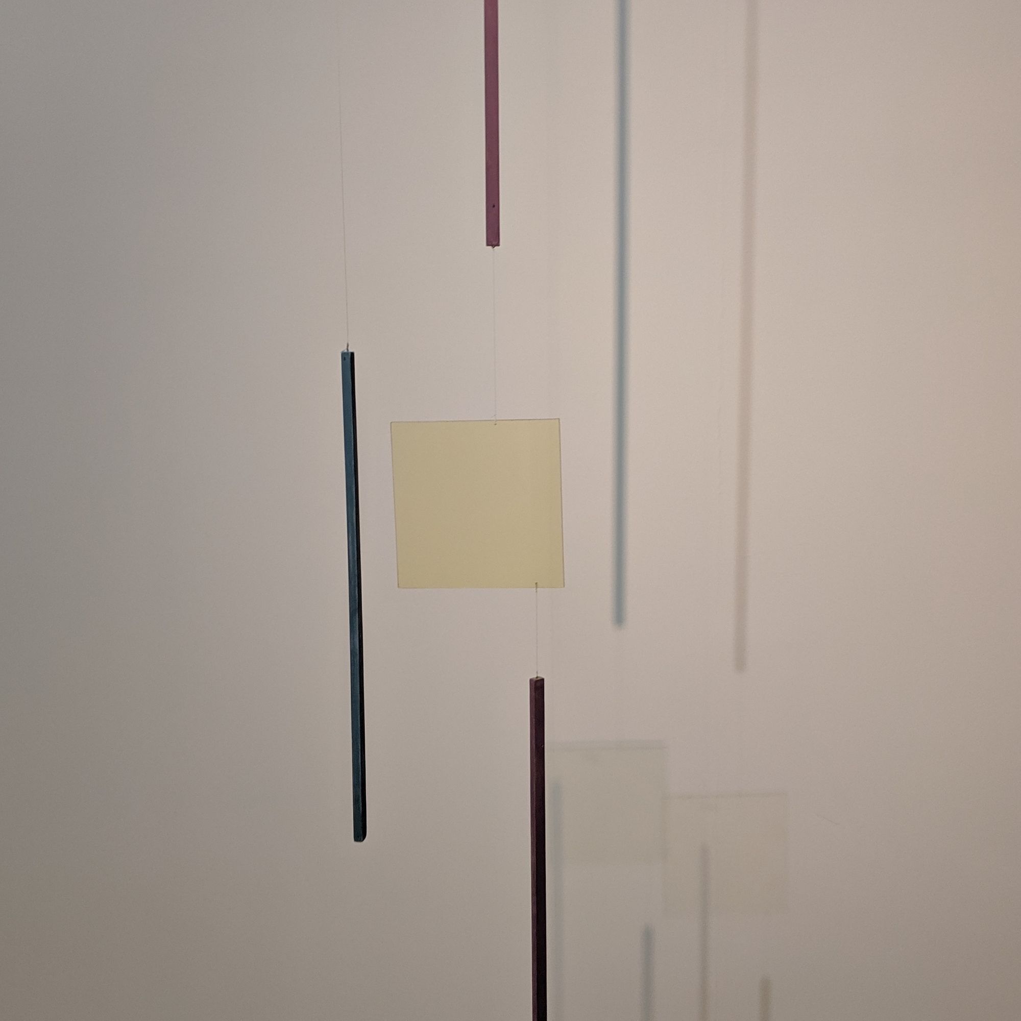
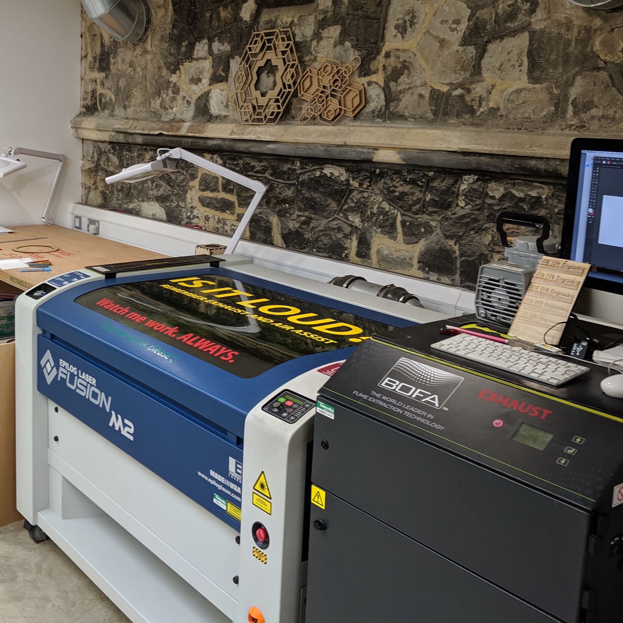
I made some fairly basic SVGs of mobiles using D3 and decided to try out laser cutting them at the Hatchlab. It was not a success at all! I hadn't yet accounted for the mass of the beam in my code, plus there were scaling issues which mean it was far off balance. As I work full time getting access to the laser cutter was tricky so I had to do a lot of measuring and experimenting at home in the evenings. Towards the end of the project, I started using the laser cutter at the London Hackspace as I could get late-night access and there was no queue of fellow students.
With some maths advice from my girlfriend, I figured out how to account for the mass of the beam in the equation and the images which the code produced started to at least look like they should balance.
I decided to split my code up into modules and used Svelte to assist with this. It became much easier for me to then separate the code in the model which was controlling the dimensions of the tree from the code which rendered the tree to the screen. I was then also able to add another render which was optimised for cutting the mobile from sheets of acrylic.
I now had some output which looked promising so I started to add variability to the generation of mobiles. I used dat.GUI to make a basic editor for playing around with variables. In the end, I settled on the following variables:
- Mass - since I was using a uniform material this translated directly into the area of the hanging shape
- Beam length - as force is equal to mass × distance the beam length has as big an effect as the mass but visually perhaps is the strongest
- Drop length - the drop length matters from to prevent masses crashing into each other, but in terms of mass I ignored it for simplicity as the monofilament I was using is very light compared to the rest of the mobile
- Branching - I had two variables to control how much the tree would branch to the left and the right. In some sense left and right doesn't matter since the mobile can rotate 180° reversing each beam, but in practice, the mobile tends to find equilibrium near to the original angle
- Pointy top - As I was using only equilateral triangles, I wanted to have control over which masses were pointing up and down, especially as an up/down pair can be nearby without clashing
I then got quite stuck on creating the genetic algorithm. I wanted the tree to be of variable depth and so the number of beams and nodes would need to vary, and I wanted to apply further variations to each beam and node. I chatted to Andy Lomas about this problem, as all the examples I have seen had a fixed length DNA and he advised me to stick with that principle otherwise breeding and mutating the DNA would become complex. I was using a lot of random function calls within my code which meant each time I ran it I got a completely different tree, so there was nothing to evolve from or towards.

I had a small improvement when I switched my random function to be seeded so that I could pick a given seed and then adjust the amount that the DNA applied to the phenotype of the mobile. However, this was still far from ideal as the same seed always produced the same tree, so the genetic algorithm could only seek to find the best parameters for that tree. There was no way of merging two seeds together without ending up with a completely different tree which was nothing like either of the two parents. I struggled with this idea for ages and then eventually realised I could use random noise! I changed my code so that the seed now just generated the noise and then all the randomness came from the position on the noise. Now when two DNAs were merged they could become closer to each other on the continuous varying noise function. Sometimes this still meant wild changes, but it could allow them to settle and find local maxima.
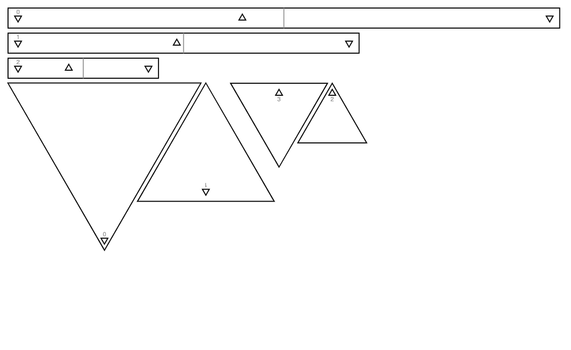
Now that I had my genetic algorithm working, I set about tuning my fitness function. Initially, I had just been using a simple function to get the total mass of the mobile to target a given number. An early and important idea was to use it to remove or reduce the chance of parts of the mobile clashing or bumping into each other. I thought about how to achieve this and came up with the plan to render the mobile to an HTML Canvas with 50% transparency and then count the number of pixels which had opacity above 50% and normalised by the total area of the mobile. The fitness would target reducing this overlap area to zero.
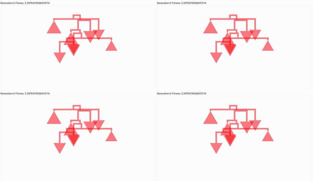
This plan worked out pretty well. The above animation shows some of the results. I made the vertical drops much thicker than they would be in the physical version so that the algorithm would "try harder" to remove this overlap too. It worked pretty well but tended towards finding very simple small mobiles, so I added to the fitness to prefer more nodes and a larger diversity of sizes which increases the complexity and interest.
Future development
I plan to continue developing this work as I've found it really exciting and had lots of positive feedback about it so far. The natural progressions I would like to make are to extend the range of shapes for the masses, initially to cover other regular geometric shapes, but then ideally any shape including calculating the negative mass of holes. I would also change my code to deal directly with mass instead of the area so that I could incorporate other items, such as found objects into my mobiles. I would also like to be able to extend the total size and mass of the mobiles - this will require a lot more research into the materials since my prototypes were already reached the limits which caused the beam to bend.I would also like to develop a clearer narrative behind mobiles produced from this work so that I could use the concept of balance to compare and contrast ideas and representations as part of the manifest form of the mobile.
Self evaluation
Overall I was very pleased with the outcome and amount achieved with this project. Every step was more complex and took longer than I had hoped for, but I eventually got to where I wanted. I would have liked to have made a bigger mobile, but I found I was closer to the constraints of the materials which caused the beams to begin to bend.
References
- Realist manifesto - http://www.terezakis.com/realist-manifesto.html
- D3 - https://d3js.org use of d3-hierarchy, d3-randomLogNormal, d3-scaleLinear, d3-extent, d3-descending
- GeneticJS - https://github.com/subprotocol/genetic-js code to run genetic algorithms
- PF Perlin - https://www.npmjs.com/package/pf-perlin for generating Perlin noise
- Svelte - https://svelte.dev for component architecture
- Lodash - https://lodash.com for debounce and object clone
Thanks to Brittany Harris for helping me with maths, code reviews and general help and patience with this project